


If you need the short answer: ASHRAE Standard 111 is the U.S. field standard many teams use to test, adjust, balance, and report HVAC system performance before closeout.
I’d sum it up like this: if you’re working on TAB, this standard tells me what to measure, how to check system readiness, how to balance air and water, and what must go into the final report. It also ties straight into closeout, final inspection, and, in many jobs, the path to a Certificate of Occupancy.
Here’s the plain-English version:
- What it covers: air systems, hydronic systems, and related controls
- Current edition: ANSI/ASHRAE Standard 111-2024
- What gets measured: CFM, GPM, pressure, and temperature
- Common field target: around ±10% of design for airflow and water flow
- Instrument check cycle: at least every 12 months
- Calibration trigger: if readings differ by more than 2%
- Typical room pressure range: ±0.01 to 0.05 in. w.g., based on space use
- Why it matters: the TAB report helps support punch-list closeout, inspection review, and occupancy approval
If I were reducing the whole article to one point, it would be this: ASHRAE 111 turns TAB from “take some readings” into a documented field process with set measurements, set steps, and a report that other people can verify.
A few points stand out:
- You don’t start with instruments. You start with drawings, schedules, sequences, and readiness checks.
- You don’t just measure once. You test, adjust, balance, and then verify again.
- You don’t stop at field data. You finish with a TAB report that shows design vs. measured values, instrument data, final settings, and open issues.
That means the standard is not just about airflow at diffusers. It also covers fan RPM, motor amps, static pressure, coil conditions, pump pressure, valve settings, VFD speeds, and water-side checks.
One small comparison helps show the flow:
| Area | Main focus | Common units | Usual check |
|---|---|---|---|
| Air side | Ducts, terminals, room pressure | CFM, in. w.g., °F | Traverse, hood, pressure readout |
| Hydronic side | Water flow, pump pressure, coil ΔT | GPM, psi, °F | ΔP readout, valve chart, temperature check |
| Reporting | Final balanced condition | % of design | Design vs. measured record |
So if you’re a contractor, TAB firm, engineer, or inspector, this article comes down to one simple idea: measure the right things, balance in the right order, and document the final condition clearly.
Measurement Methods Required by ASHRAE 111
Airflow, Pressure, Temperature, and Hydronic Flow Measurements
ASHRAE 111 spells out the field measurements contractors need to document for TAB closeout: airflow, pressure, temperature, and hydronic flow. These readings shape the TAB work that comes next.
On the air side, duct airflow is measured in CFM. ASHRAE 111 calls for duct traverses to measure airflow in ducts, while flow capture hoods or anemometers are used at terminals.
Static and differential pressure readings, in in. w.g., are taken at fans, filters, coils, and room boundaries. Room pressurization is the pressure difference between the room and the adjacent space. Many projects aim for ±0.01–0.05 in. w.g., based on the space type. Air temperatures are recorded in °F at coil entering and leaving points, and at room and outdoor locations when psychrometric data is needed.
On the hydronic side, water flow rates are listed in GPM. TAB techs read differential pressure across calibrated valves or components, then convert ΔP to GPM with the manufacturer’s chart. If there are no dedicated balancing valves, the pressure-drop method across coils can be used. The ΔT across supply and return water gives a cross-check with Q = 500 × GPM × ΔT.
Instrument Accuracy and Measurement Planning
ASHRAE 111 separates instrument accuracy from field accuracy. That matters because field conditions – like turbulence or poor test locations – can throw readings off. The standard gives average field accuracy as ±10 percent.
Instruments should be checked at least every 12 months against a reference instrument and recalibrated if the readings differ by more than 2%. Project tolerances are often ±10% of design CFM or GPM, though critical spaces may have tighter limits.
The table below sums up the main air-side and hydronic-side checks.
Table: Air-Side vs. Hydronic-Side Measurements
| Parameter | Measurement Method | Typical U.S. Units | Typical Tolerance / Accuracy |
|---|---|---|---|
| Supply/return/exhaust airflow | Pitot tube traverse; flow capture hood at terminals | CFM | ±10% of design |
| Duct static pressure | Pitot-static probe with manometer | in. w.g. | Per project spec |
| Room pressurization | Digital micromanometer (room vs. adjacent space) | in. w.g. | ±0.01–0.05 in. w.g. |
| Air temperature | Calibrated thermometer or thermocouple | °F | ±0.5–1.0°F |
| Chilled/heating/condenser water flow | ΔP across balancing valve or calibrated component; flow station | GPM | ±10% of design |
| Hydronic differential pressure | Digital differential pressure gauge | psi or ft of water | Per project spec |
| Supply/return water temperature | Calibrated thermometer or thermocouple | °F | ±0.5–1.0°F |
HVAC Air Testing & Balancing
How to Perform TAB Under ASHRAE 111
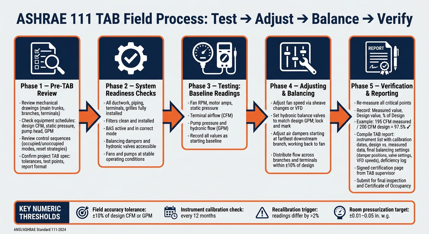
ASHRAE Standard 111 TAB Process: From Pre-Check to Closeout
Pre-TAB Review and System Readiness Checks
Once you know which measurements you need, the next job is making sure the system is ready for fieldwork. Before any field testing starts, ASHRAE 111 calls for a structured document review. In plain terms, that means going through the mechanical drawings to trace main trunks, branches, terminals, and critical spaces. It also means checking equipment schedules for design CFM, static pressure, pump head, and GPM, then reviewing control sequences, including occupied and unoccupied modes and reset strategies, so the field data lines up with the submittal requirements. The project TAB spec also matters here because it defines tolerances, test points, and the report format.
System readiness checks matter just as much as the paperwork. All ductwork, piping, terminals, grilles, and control devices should be fully installed, with no temporary caps or missing parts. Filters should be clean and installed. The BAS needs to be active and in the correct mode. If it isn’t, airflow and temperature can drift, and the readings won’t mean much. Balancing dampers and hydronic valves also need to be accessible for adjustment, and fans and pumps should run long enough for operating conditions to settle before measurements begin.
Testing, Adjusting, Balancing, and Verification Steps
The field sequence is simple: test, adjust, balance, verify.
Testing starts with baseline readings. Record fan RPM, motor amps, static pressure, terminal airflow, and hydronic flow. Record main, branch, and terminal airflow readings. Record pump pressure and hydronic flow.
Once that baseline is set, adjusting begins. Fan speed is brought to target with sheave changes or VFD adjustments, using fan laws and measured RPM to guide the change. Hydronic balance valves are set by matching measured GPM to design, then locked and marked. On the air side, main and branch dampers are adjusted starting at the farthest downstream branches and then working back toward the fan. That order helps keep the system steady while settings are dialed in.
Balancing is where flow gets distributed across branches and terminals so each zone lands within the specified tolerance. Then comes verification, the final check. Key points are measured again to make sure earlier changes didn’t throw other areas off. Each value should be recorded as measured, design, and percent of design. For example, if a terminal measures 195 CFM against a design value of 200 CFM, it is reported as 97.5% of design, which falls within a common ±10% terminal tolerance. Those readings go straight into the TAB report and closeout package.
Table: TAB Phases and Required Field Data
| TAB Phase | Purpose | Field Actions | Readings |
|---|---|---|---|
| Testing | Establish baseline system performance | Record fan RPM, motor amps, static pressure, terminal airflow, and hydronic flow | Fan CFM, in. w.g. static pressure, terminal CFM, pump GPM, motor amps |
| Adjusting | Bring major components to design targets | Sheave changes or VFD speed adjustments, balance valve positioning | Revised fan RPM, adjusted GPM, updated static pressures |
| Balancing | Distribute air and water flow across branches and terminals | Damper and valve adjustments from the farthest terminal back to the source | Branch and terminal CFM or GPM as % of design |
| Verification | Confirm final system performance | Re-measure critical points, cross-check against design and spec tolerances | Final CFM, GPM, °F supply/return temperatures, % of design for all key points |
Reporting Requirements and Closeout Deliverables
What an ASHRAE 111 TAB Report Must Include
Once field verification is done, the data needs to end up in a form people can actually use. An ASHRAE 111-compliant TAB report is that record. It serves as a formal closeout document and gives the project team a traceable record for what was tested and how the system was left.
At a minimum, the report should include project identification, a system summary, testing conditions, the balancing method, and design-versus-measured data for airflow, water flow, pressure, and temperature. Just as important, it should show the final balanced condition so someone can come back later and verify the results.
Many project specs also require system and terminal data sheets for each outlet, terminal unit, coil, pump, and main. Those sheets usually include setpoints, damper or valve positions, and final flow values. The instrument list matters just as much. Every flow hood, manometer, differential pressure gauge, and hydronic meter used in the field should be listed with its manufacturer, model, serial number, and latest calibration date.
The report also needs to record final balancing settings such as damper positions, valve settings, VFD speeds, and control setpoints, so future techs can verify or restore the balanced condition. If something couldn’t be corrected through adjustment alone, it should go into a dedicated deficiency log. Each item should include a unique ID, location, system reference, description, and the effect on system performance.
A signed certification page from the TAB supervisor wraps up the report and confirms the work was done under ASHRAE 111 and the project procedure standard. That’s the paperwork owners and inspectors look at during closeout.
How TAB Reports Support Final Inspection and Occupancy
At project closeout, the TAB report becomes the record used to verify compliance and support occupancy approval. Inspectors and the AHJ use it to confirm that air and water systems are operating within project tolerances. Outside air quantities, exhaust flows, and pressure relationships are documented in the same report, which helps support mechanical code compliance for ventilation and smoke control.
Many jurisdictions that follow the International Mechanical Code require a certified TAB report before issuing a Certificate of Occupancy or closing out a mechanical permit. So this isn’t just admin work. It’s often a direct step in getting the building approved for use.
The deficiency log also gives the general contractor a clear HVAC punch list before final inspection. That can cut down the chance of a failed inspection and the delays that follow.
The TAB report is also appended to the O&M manuals by reference, giving facility managers a baseline for future troubleshooting and maintenance.
Table: Minimum Report Items vs. Closeout Deliverables
| ASHRAE 111 Minimum Report Item | Common Project Closeout Deliverable |
|---|---|
| Project identification and system descriptions | Signed certification page from TAB supervisor and field leader |
| Design vs. measured values (CFM, GPM, °F, in. w.g.) | Test point reference diagrams keyed to mechanical drawings |
| Instrument list with calibration dates | Deficiency log with status (corrected, open, accepted as-is) |
| Final balancing settings (dampers, valves, VFD speeds) | O&M manual attachment with terminal schedules |
| Operating conditions during testing | Final certified report submitted digitally to owner and engineer of record |
| Deficiency and deviation list | Updated re-certification after corrective work is completed |
Conclusion: Applying ASHRAE 111 for a Reliable TAB Process
After testing, balancing, and reporting are done, ASHRAE 111 becomes the record behind final acceptance. It lays out the TAB field method for measuring, adjusting, balancing, and reporting HVAC performance. That gives owners, contractors, TAB firms, engineers, and AHJs a common benchmark for how results should be documented.
Since the report becomes part of closeout, field accuracy and documentation matter just as much. The final report needs to show calibrated instruments, measured-versus-design data, and any open deficiencies. That record supports final inspection and occupancy approval.
Set acceptance tolerances before fieldwork starts to avoid closeout disputes.
Air Balance Masters provides certified TAB testing, reporting, and certification services for contractors in MD, VA, PA, NJ, NY, DE, and DC.
FAQs
Who needs ASHRAE 111?
ASHRAE Standard 111 is for people who work in HVAC testing, adjusting, and balancing (TAB), including TAB technicians, engineers, and HVAC contractors.
It lays out a technical framework for measuring and balancing HVAC systems so they can meet design specs and local rules tied to Certificates of Occupancy. It also helps teams produce accurate, consistent documentation during project closeout.
When should TAB start on a project?
TAB should start after all mechanical systems are fully installed and working, but before occupancy. That timing matters.
It gives the team a chance to check system performance and confirm everything lines up with the design specs before final inspections and the certificate of occupancy.
Before the TAB team shows up, the site needs to be ready. That includes a sealed building envelope and confirmation that the equipment is ready for testing.
What can cause a TAB closeout to fail?
A TAB closeout can fail for two simple reasons: the numbers don’t match the design, or the paperwork doesn’t hold up.
If the final supply, return, or exhaust airflow readings fall outside ±10% of design, that’s a problem right away. The same goes for reports with missing information, bad data, or no calibration details. If someone reviewing the closeout can’t tell how the readings were taken or whether the instruments were checked, the report may not pass.
Closeouts can also be rejected when open issues are still sitting on the table. For example, if duct leaks, control problems, or other physical defects weren’t fixed before testing, the TAB report may be treated as incomplete. And there’s one more point that often trips people up: the report may be turned down if it comes from the same company that installed the system.


