


An air balance report confirms whether an HVAC system is performing as designed. It provides detailed data on airflow, system performance, and compliance with industry standards. These reports help building owners and inspectors ensure HVAC systems meet design specifications, pass inspections, and operate efficiently. Here’s what every air balance report must include:
- Airflow Measurements: Compare design vs. actual airflow to identify issues like duct leaks or clogged filters.
- System Performance Data: Evaluate total airflow, motor performance, and building pressure to ensure proper operation.
- Equipment Schematics: Visual references like drawings and layouts help confirm system alignment with design.
- Deviations and Notes: Document discrepancies and corrective actions for unresolved issues.
- Compliance Documentation: Certify the system meets standards like ASHRAE guidelines to avoid inspection delays.
These components ensure the HVAC system is tested thoroughly and documented accurately for long-term reliability.
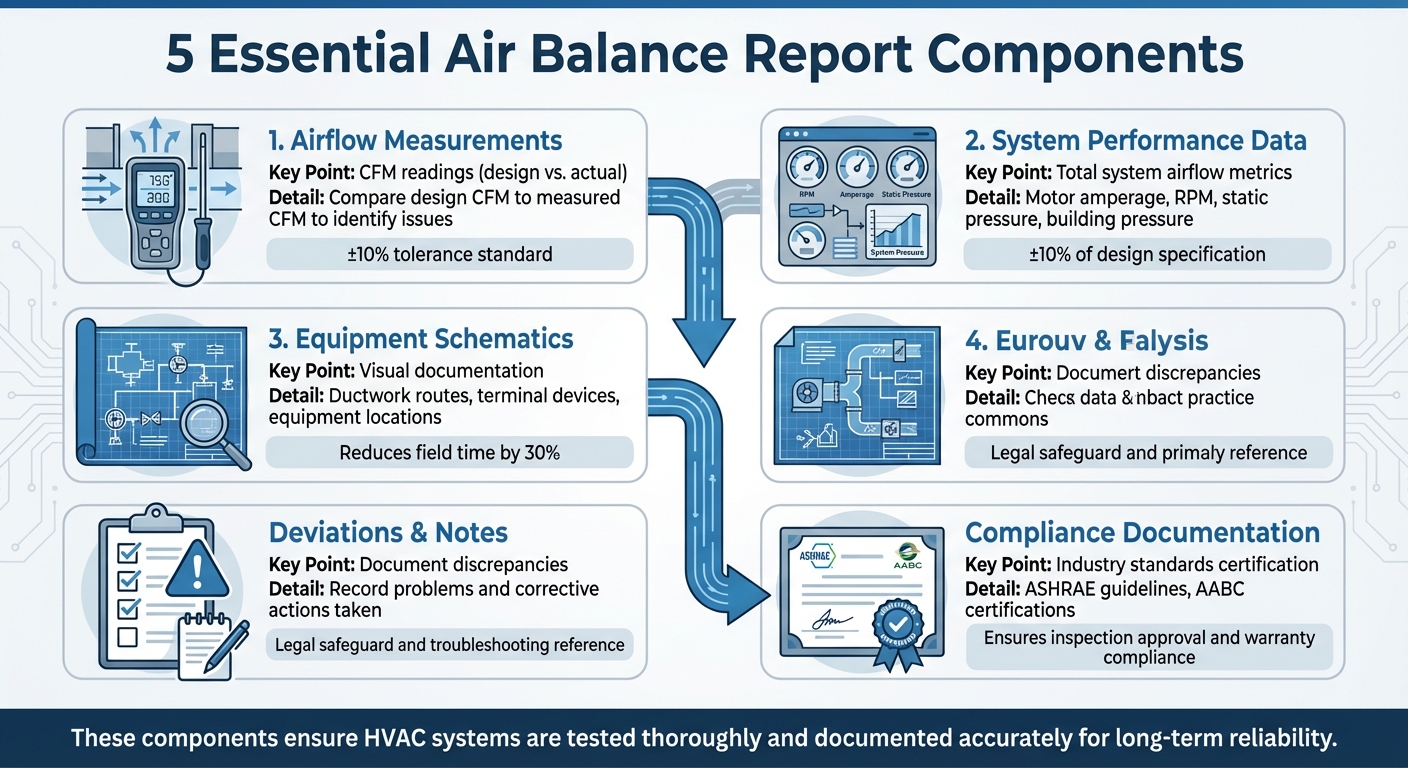
5 Essential Components of an Air Balance Report
HVAC – Air Side: Air Balance Basics for Commercial Facilities
1. Airflow Measurements
Airflow measurements are a cornerstone of any air balance report, serving as the foundation for evaluating a system’s performance. These readings, expressed in Cubic Feet per Minute (CFM), reveal the actual volume of air moving through the system and are essential for pinpointing potential issues.
The report should include both the design CFM (specified by the engineer) and the actual CFM (measured in the field). Comparing these values can quickly uncover discrepancies. For instance, if a supply register is designed to deliver 150 CFM but only measures 110 CFM, that 40 CFM difference signals a problem. This could stem from a damper adjustment, duct leakage, or even something as simple as a clogged filter.
Technicians rely on specialized tools to gather these measurements. They use flow hoods for direct CFM readings, anemometers to calculate CFM from air velocity, and pitot tubes to determine airflow based on pressure differences. Accurate readings depend on using these tools correctly and conducting thorough preparation.
Before taking measurements, the system should run for at least 15 minutes to stabilize. Filters and coils must also be clean to avoid skewing the results. To streamline the process, experienced technicians often review project plans ahead of time, marking and numbering each supply register and return grille. This step minimizes delays and ensures a systematic approach in the field.
For clear documentation, each outlet should be recorded with its room location, identifier, design CFM, and measured CFM. This detailed record allows for quick verification during on-site inspections.
2. System Performance Data
A thorough air balance report goes beyond just individual airflow measurements. It should encompass system-wide performance metrics to assess how the entire HVAC system functions under actual operating conditions. These metrics confirm whether the installed system aligns with the original design specifications. Here’s what to include when evaluating system-wide performance:
- Total System Airflow: Combine the supply, return, and outside airflows to get a full picture of the system’s overall performance.
- Component Operational Parameters: Record critical data for components like furnaces, condensing units, air handlers, exhaust fans, and heat recovery ventilators. Pay attention to motor amperage, RPM, and external static pressure. For example, motor amperage readings that exceed manufacturer specifications could signal issues like pressure losses, installation errors, or mechanical friction – factors that can reduce equipment lifespan.
Building pressure measurements are another key aspect. The pressure relationship between a building’s interior and the outdoors directly impacts system efficiency and occupant comfort. This is especially critical in environments like hospitals, where proper pressurization helps prevent contamination. Additionally, monitoring supply and return temperatures can provide insights into coil performance. Abnormal readings might point to problems like clogged coils or incorrect water flow.
For airflow readings, the acceptable tolerance is usually ±10% of the design specification unless project documents specify otherwise. Presenting this data in clear tables that compare design values to actual measurements makes it easier to spot discrepancies at a glance.
3. Equipment Schematics and Design Drawings
Visual documentation plays a critical role in ensuring the installed HVAC system aligns with its original design. Equipment schematics and design drawings act as a reference point, detailing key data like the required Design CFM for each register and grille. This information serves as a baseline for comparing actual field measurements.
These drawings do more than just show equipment locations – they map out ductwork routes, terminal device placements, and highlight potential clashes with other building systems, such as plumbing or electrical components. Elevation and isometric views provide additional clarity, confirming that components are installed at the correct height and orientation. They also pinpoint hidden elements like dampers, sensors, and valves, which are critical for testing and verification. Essentially, these visuals streamline pre-field preparation, setting the stage for smoother operations.
Effective preparation includes organizing project plans with strategies like color-coding drawings – using blue for supply registers, red for return grilles, and yellow for equipment – and systematically numbering outlets starting from the furthest point. These steps can cut field balancing time by as much as 30%.
Accurate schematics are indispensable not only for initial testing but also for resolving issues that arise during system checks. For troubleshooting, the original drawings help trace ductwork and locate blockages. Without detailed and up-to-date HVAC drawings, the process can result in wasted energy, higher costs, design flaws, and compliance setbacks. Modern BIM tools further enhance accuracy, minimizing planning and installation errors.
Additionally, manufacturer data complements these schematics, allowing for quick on-site verification when needed.
4. Deviations and Narrative Notes
After analyzing the detailed airflow and system performance data, documenting deviations is crucial to maintaining the integrity of the report. HVAC systems often deviate from their original designs, so it’s essential to record any differences between the planned specifications and the actual field measurements. Air balance reports should always include a column for "required" design airflow (CFM) alongside an "actual" column for field-measured data. This setup helps identify and address any performance gaps.
When imbalances can’t be resolved on-site, narrative notes become vital. These notes provide the Engineer of Record with the necessary details to develop a technical solution. They can also highlight issues such as installation errors, blocked ducts, or high motor amperage, which may indicate pressure losses. Peter Diperna, a Mechanical Technical Specialist at Fitzmeyer & Tocci Associates Inc., emphasizes this point:
"It is incumbent upon the balancing technicians to provide an explanation of the issue and what corrective actions were invoked in the field to rectify the issue".
This documentation of deviations lays the groundwork for targeted corrective measures.
Reports must include both the problems identified and the corrective actions taken. Technicians should clearly outline the steps they’ve already attempted during testing and recommend solutions for issues that remain unresolved. For example, if airflow exceeds design specifications by more than 10%, the notes might suggest adjusting the VFD speed or modulating dampers. In cases where air terminal devices are inaccessible, technicians should flag this with a note such as "Not accessible", as this could delay final approval and signal the need for installing access panels.
Beyond just addressing technical issues, detailed documentation also serves as a legal safeguard. Organized narrative notes can protect balancing firms from liability, especially in retrofit projects. Pre-design reports, which document the state of equipment before any new work begins, are particularly valuable in these cases. Using digital forms that include photos and equipment data can further reduce the potential for disputes. Digital records also simplify on-site validation and compliance processes. The ultimate goal is to create a report format that allows the technician to walk the job site with the owner or commissioning agent, pointing out specific problems and explaining the necessary corrective actions in real time.
5. Compliance Documentation
Compliance documentation serves as the final step in completing an air balance report, providing proof that the HVAC system adheres to established industry standards.
Every air balance report must include the necessary certifications and regulatory records to confirm that the HVAC system has been tested and balanced according to recognized guidelines. This documentation is critical, as it officially verifies compliance with technical standards. Without it, you could face delays in final inspections and project closeouts.
A key element of compliance documentation is following ASHRAE’s technical guidelines. Certifications from organizations like AABC, combined with adherence to ASHRAE standards, demonstrate that the system meets national performance specifications [13]. These records give building owners, commissioning agents, and inspectors confidence that the system operates as intended.
During inspections, compliance documentation simplifies the process for inspectors. By comparing the required design CFM with the measured values, they can quickly confirm performance. Rob "Doc" Falke, President of the National Comfort Institute, highlights the value of a well-prepared air balance report:
"A clear and readable air balance report can be on-site verified with the balancer walking the job with the owner or commissioning agent in a fraction of the time it takes to balance a project".
This transparency allows inspectors to evaluate the performance of individual components, from supply registers to exhaust fans. Including manufacturer-provided equipment engineering data further supports the claim that the system operates within its specified parameters.
To ensure smooth inspection approvals, gather project plans and specifications ahead of time. The final report not only provides a permanent, traceable record but also supports warranty compliance, offering protection for all parties involved.
What a complete air balance report includes
Every piece of an air balance report – whether it’s precise airflow readings or records of deviations – serves a key purpose in verifying how well an HVAC system is performing. By bringing together airflow data, system performance metrics, schematics, and compliance records, the report provides a clear and actionable overview of the system’s efficiency and adherence to standards.
Creating a thorough report requires skilled technicians armed with calibrated tools. These professionals are trained to spot subtle installation problems, like poorly designed duct transitions or high motor amperage, that might lead to inefficiencies down the line. Plus, good preparation in the office before heading into the field can make the whole process smoother and more efficient.
FAQs
Why is it important to compare design airflow with actual airflow in an air balance report?
Comparing the planned airflow with the actual airflow measured on-site is a key step in ensuring an HVAC system is working as it should. This process confirms that the system provides the right temperature control, maintains occupant comfort, and supports indoor air quality as laid out in the original design.
When differences are detected, they can point to issues such as undersized ductwork, improper damper settings, or fan speed misalignments. Fixing these problems helps the system run more efficiently, eliminates uneven temperatures, and ensures compliance with commissioning requirements or green building standards. This comparison plays a vital role in verifying that the system meets its design goals and operates dependably.
How do equipment schematics help verify the performance of an HVAC system?
Equipment schematics offer a clear, visual map of an HVAC system, detailing the arrangement of key components like air-handling units, ducts, diffusers, and control devices. They also pinpoint the exact spots where airflow, pressure, and temperature readings were taken. This makes it easier to verify whether the system’s performance matches its design specifications and to spot problems – like a diffuser not delivering enough airflow or a fan running outside its intended range.
Including these schematics in an air balance report helps engineers, contractors, and commissioning agents compare real-world measurements with design plans and equipment specs. This not only ensures the system meets project requirements but also identifies deviations and streamlines troubleshooting or warranty claims when necessary.
Why is compliance documentation important for HVAC system inspections and approvals?
Compliance documentation plays a crucial role in HVAC inspections, serving as proof that the system adheres to all design, installation, and performance standards. These records include key details like load calculations, equipment specifications, system-balancing data, and commissioning reports. Together, they demonstrate that the system meets relevant codes, climate-zone requirements, and project guidelines, ensuring it operates safely and efficiently.
Inspectors and reviewing authorities rely heavily on these documents to verify accuracy and spot any discrepancies or omissions. A complete and precise set of compliance documents is mandatory – not just before fieldwork begins, but also prior to final inspections. Without this paperwork, the system cannot gain approval, certification, or occupancy permits. Simply put, compliance documentation ensures HVAC systems function as designed and fulfill all regulatory and contractual requirements.


