


If HVAC noise shows up at closeout, I’d treat it as a measured system problem – not a mystery. In most cases, the issue comes back to too much airflow, too much static pressure, the wrong fan speed, weak isolation, duct transmission, or unstable controls.
Here’s the short version:
- Airborne noise usually sounds like hiss, whistle, or fan roar
- Structure-borne vibration often shows up as hum, rumble, or rattling through walls, slabs, or supports
- TAB checks cfm, static pressure, fan rpm, sound, and vibration
- Main comfort-system duct speeds are often kept near 1,500 fpm or less, with branches near 800 fpm or less
- Many office targets land around NC 30–35, while conference rooms may be NC 25–30
- Balancing to design airflow at the lowest static pressure the system needs can trim noise and fan energy; some projects see 10%–20% lower fan energy after fan-speed optimization
What I’d want from TAB is simple:
- proof of the complaint
- proof of the cause
- proof of the fix
- proof from the retest
That means the report should tie each reading to a location, system condition, and piece of equipment, then show the before-and-after results. If the paperwork is weak, closeout can stall. If the data is solid, the team can move toward final inspection with fewer surprises.
Bottom line: this article shows how TAB turns HVAC noise and vibration complaints into field data, points the fix to the right trade, and supports final approval and turnover.
Imbalanced Blower Wheel Causing Vibration
Common Causes of HVAC Noise and Vibration in Commercial Systems
Once closeout brings a complaint to the surface, TAB usually narrows it to four source categories: airflow and distribution, fan and mechanical defects, duct and structure transmission, and controls instability.
Airflow and Distribution Problems
Undersized ducts, sharp elbows, and abrupt transitions can drive up velocity and turbulence. That’s what creates the hiss or whoosh people notice first. Industry guidance recommends keeping main duct velocity at or below 1,500 fpm and branch duct velocity at or below 800 fpm in comfort systems.
Diffusers can also add noise if they’re placed too close to branch takeoffs or installed without a few feet of straight duct ahead of them. In those cases, buzzing or resonant noise may show up downstream.
To sort this out, TAB technicians measure airflow volume (cfm), duct velocity (fpm), and static pressure (in. w.g.) at key points, then compare those readings with the design targets. A common red flag is high diffuser neck velocity paired with low cfm in nearby branches. That usually points to imbalance, which can often be corrected with a damper change or fan-speed adjustment.
Fan, Equipment, and Installation Defects
If the complaint sounds more like a hum, drone, or steady vibration than rushing air, the source is often the fan assembly or the mechanical installation.
Fan wheel imbalance is one of the most frequently cited causes of elevated vibration and resonant noise. Misalignment between motor and fan sheaves can add belt-frequency vibration and speed up wear. Loose fasteners or poor equipment support often lead to rattling that travels through the structure. Incorrect belt tension can create slippage noise and may push bearings outside their intended load range.
Fans operating far from their design point are another common source. When system resistance is higher than design because of blocked filters or coils, throttled dampers, or field changes, the fan can get pushed toward stall or surge. That often leads to loud, fluctuating sound.
TAB technicians check this by measuring fan rpm and plotting the measured operating point on the fan curve. They also inspect the fan assembly for balance, alignment, belt condition, and fastener tightness.
Duct, Structure, and Controls Issues
Structure-borne noise and controls instability round out the four categories, and both can be easy to misread without field data.
Missing flexible connectors, poor hangers, or rigid attachments can let vibration pass into the structure. TAB teams track this by measuring vibration at the equipment, supports, and nearby structural elements, then checking whether levels drop off with distance. If they don’t, the isolation path has likely been compromised.
Controls instability looks different. It tends to show up as fluctuating airflow, hunting dampers, or noise that changes with load instead of staying steady. When static pressure setpoints are too high, VAV boxes overthrottle to hold zone conditions. That drives up duct velocity and diffuser noise.
TAB teams compare control trend logs, damper positions, and measured static pressure with room conditions to pin down whether the noise is coming from the controls sequence or from the hardware itself.
The table below maps each cause category to its usual symptom and the main TAB measurement used to confirm it:
| Cause Category | Typical Symptom | Primary TAB Measurement |
|---|---|---|
| Airflow and distribution problems | Hiss, whistle, whoosh, draft complaint | Airflow (cfm), duct velocity (fpm), static pressure (in. w.g.) |
| Fan, equipment, and installation defects | Hum, drone, vibration at fan speed, rattle | Vibration velocity/acceleration, fan rpm, operating point vs. fan curve |
| Duct and structural transmission | Low-frequency rumble, noise transfer between rooms | Vibration at supports and connections, NC readings in occupied spaces |
| Controls instability | Hunting, surging, noise that varies with load | Control trend logs, static pressure trends, damper position data |
TAB then confirms the active cause with airflow, vibration, and control readings.
TAB Field Checks and Diagnostic Methods
When noise or vibration shows up at closeout, TAB starts with the drawings, specs, and the stated noise criteria. The point is simple: check the complaint against the design, not make a guess. TAB first separates airflow issues, equipment issues, and transmission issues before any corrective work begins.
Pre-Test Review and On-Site Observations
After the likely cause is narrowed, TAB confirms it with field measurements. Before any testing starts, the TAB team reviews drawings, specifications, equipment schedules, and project-defined noise criteria, such as NC or RC targets. That review sets the baseline for expected airflow, fan performance, equipment locations, and required test points. In occupied spaces, common project criteria may include NC 30–35 for private offices and NC 25–30 for conference rooms.
On site, the first move is a walk-through with no instruments. The technician listens to the complaint under different operating conditions and checks ductwork, supports, fasteners, isolation mounts, access clearances, and flexible connectors for looseness, rubbing, or missing isolation. That early pass helps narrow the source before instrument testing starts.
A common early find is a vibration isolator that has been bridged by a shim, grout, conduit, or piping, which can defeat the isolation. With the system running, the technician also listens for leaks, rattles, whistling dampers, and rough fan operation. Those clues help narrow the test points.
Those observations shape which measurements matter most.
Instruments and Measurements Used in Noise and Vibration TAB
Calibrated sound level meters and octave-band analysis are used to measure overall sound pressure levels in dBA and show which frequency bands are driving the complaint. Octave-band data from 63 Hz to 8,000 Hz is especially useful because a system may look acceptable in overall dBA and still fail an NC target due to trouble in one band.
For mechanical vibration, technicians use portable vibration meters and accelerometers mounted on bearing caps or equipment feet. Vibration is reported as RMS velocity (in./sec) or displacement (mils). Pitot tubes, balancing hoods, and manometers are used to confirm cfm and static pressure, while fan rpm is recorded and checked against the design operating point.
Isolating Sources and Documenting Findings
Source isolation confirms what the complaint is actually coming from. The team measures background sound with the system off, then repeats the test with the equipment running to isolate its contribution. If more than one system is operating in the same area, individual fans, pumps, or air handlers are isolated one at a time.
Vibration readings are taken in vertical, horizontal, and axial directions because each direction can point to a different mechanical problem, such as misalignment, looseness, or imbalance. Acceptable vibration limits are then compared with ASHRAE equipment vibration criteria.
Each deficiency should be documented with:
- Initial and final readings
- Probable cause
- Corrective action
- Retest status
Those readings become the basis for correction and retest documentation.
Airflow Balancing, Fan Performance, and Noise Reduction
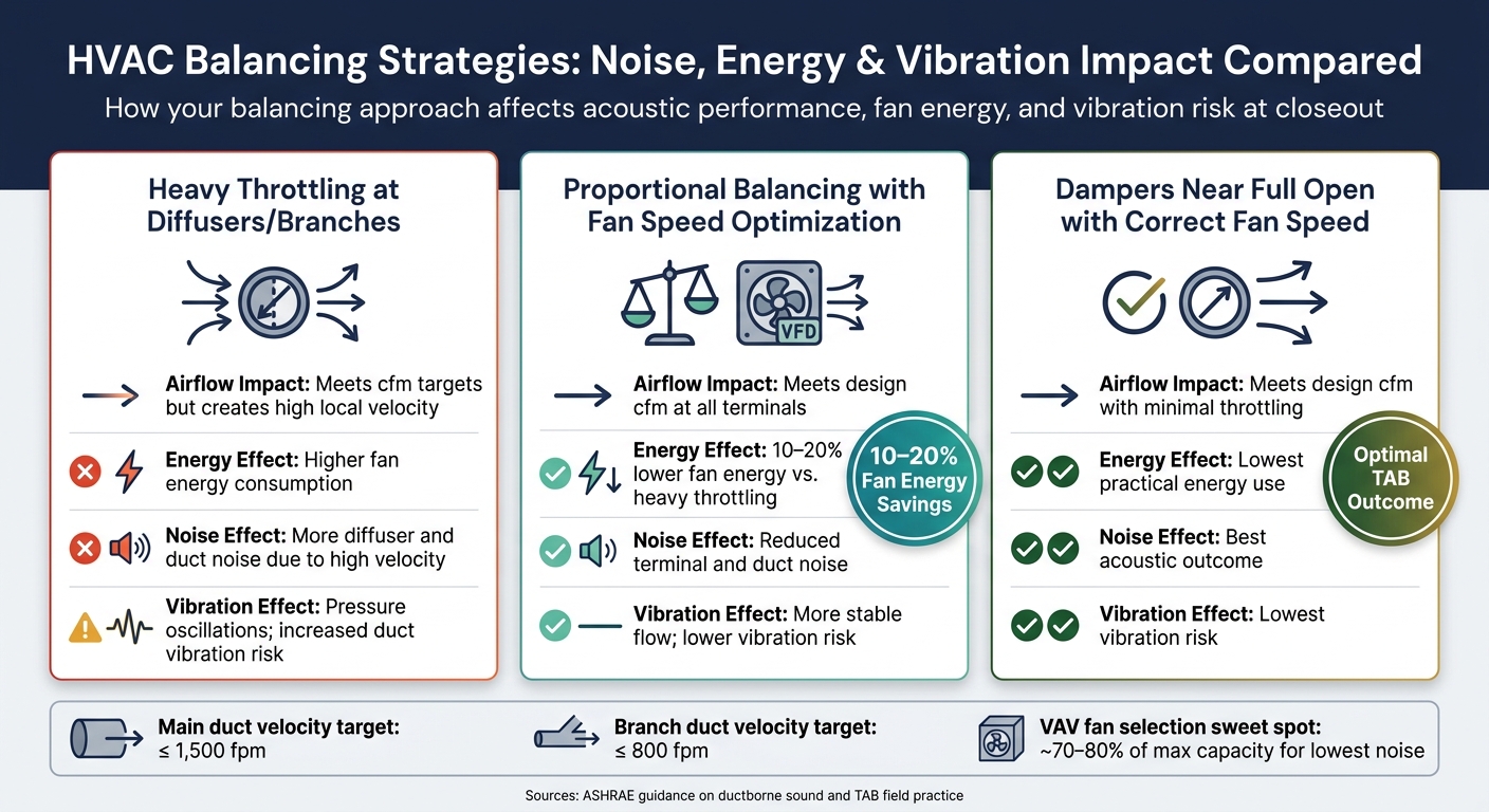
HVAC Balancing Strategies: Noise, Energy & Vibration Impact Compared
Once TAB shows airflow is the source of the problem, balancing becomes the main fix.
How Design Airflow and Static Pressure Affect Sound Levels
When TAB confirms airflow is the cause, the fix is to reset fan speed and damper positions to design conditions – not to keep choking down terminals.
Too much static pressure forces air through dampers and openings at higher velocity. That drives up outlet noise. ASHRAE guidance says ductborne sound can rise at about the fifth to seventh power of airflow velocity near fittings, transitions, and terminals. In plain terms, a small jump in airspeed can turn into a much louder system. Keep velocities within project limits, and keep branches and runouts slower than mains.
TAB balances the system to design cfm at the lowest practical static pressure. The usual approach is simple: open dampers as much as possible, then trim fan speed until the most restrictive outlet just reaches design cfm. Done right, airspeed drops across the system, and diffuser noise often falls by several dB in occupied areas.
Fan Speed, Operating Point, and Resonance Risks
After airflow is corrected, fan speed becomes the next control point.
Fan noise is lowest when the fan runs near its point of maximum efficiency. Move away from that point, and noise goes up.
Changes to sheaves or VFD settings shift the fan along its curve, which changes airflow, static pressure, and sound. If a fan runs faster than the system needs, it gets pushed into higher-pressure regions where efficiency falls and tonal noise becomes more obvious. That’s the hum or whine tied to blade-pass frequency.
In duct systems that don’t match the fan well, running too far from the design point can also lead to surge or stall. When that happens, airflow separates and reattaches at the fan inlet, which can create pulsing sound and vibration.
For VAV systems, fans are often selected to run near peak efficiency at about 70–80% of maximum required capacity, where sound output is usually lowest.
Balancing Strategies That Cut Rework and Energy Waste
The goal is straightforward: hit design cfm with the least static pressure possible.
Heavy throttling at diffusers or branch dampers causes two headaches at once:
- higher outlet noise
- higher fan energy use
Proportional balancing helps avoid both. The process starts by measuring airflow at all terminals, finding the outlet with the lowest actual-to-design ratio, and adjusting the other terminals to match that ratio while keeping dampers fairly open. After that, fan speed is adjusted so all terminals reach design cfm at the same time, using only the static pressure the system needs.
That matters because proportional balancing with fan speed optimization can cut fan energy by 10–20% and reduce noise complaints. Less throttling also tends to mean fewer callbacks and a smoother final acceptance.
The table below compares common balancing methods based on the items that matter most at closeout:
| Strategy | Airflow Impact | Energy Effect | Noise Effect | Vibration Effect |
|---|---|---|---|---|
| Heavy throttling at diffusers/branches | Meets cfm; high local velocity | Higher fan energy | More diffuser and duct noise | Pressure oscillations; duct vibration risk |
| Proportional balancing with fan speed optimization | Meets design cfm at all terminals | Lower fan energy | Reduced terminal and duct noise | More stable flow; lower vibration risk |
| Dampers near full open with correct fan speed | Meets design cfm; minimal throttling | Lowest practical energy use | Best acoustic outcome | Lowest vibration risk |
TAB Reports, Final Inspection, and Project Closeout
After field testing pinpoints the cause and the team makes corrections, the report turns those findings into closeout-ready documentation.
What a Complete Noise and Vibration TAB Report Should Include
A noise and vibration TAB report needs to tie every reading to a location, an operating condition, and a specific piece of equipment. That link is what makes the report useful for engineers, owners, and inspectors. It’s not just a sheet full of numbers. It’s a clear record of what was measured, where it was measured, and under what conditions.
Include project ID and test dates, operating conditions, equipment schedules, measured airflow and static pressure, fan rpm, relevant electrical data, supply and return temperatures when they affect operation, overall sound levels and octave-band data, vibration readings at equipment and nearby structure points, and octave-band plots against NC curves.
Just as important as the measurement data is the deficiency section. Each deficiency should spell out the observed condition, the likely cause, the correction made, and the responsible trade if work still remains. Retest results should sit next to the original readings so the contractor can show the issue was resolved without sending a separate document.
The report should also include instrument model numbers, calibration dates, firm certification, and the supervisor’s stamp and signature. Those details help the report hold up during owner, engineer, and inspector review.
That documentation closes the loop with the AHJ and the project team.
How TAB Reports Support Inspection Approval and Certificates of Occupancy
A complete TAB report gives the AHJ, engineer, and project team documented proof that the system meets design intent and that any noise or vibration deficiency was corrected.
When the report is well organized, final inspection tends to move faster because it shows exactly what failed, what changed, and what the retest confirmed. An inspector can follow the trail without guesswork: which noise or vibration issue was flagged, what adjustment was made, and what the retest showed.
The report also matters after inspection. For the facility team, it becomes a baseline record. If a space starts showing vibration trouble after turnover, the original report shows what the system measured at handoff. That makes it much easier to tell whether the problem is new, recurring, or tied to a deficiency that was never fully resolved.
Once the report is accepted, the next step is using TAB findings to stop the same problems from coming back.
Key Takeaways for Resolving HVAC Noise and Vibration with TAB
In day-to-day work, TAB resolves noise and vibration by turning complaints into measured deficiencies that can be fixed.
These complaints usually trace back to things you can measure: excess airflow, wrong static pressure, incorrect fan speed, poor isolation, duct resonance, or control instability. A systematic set of field checks – pre-test review, on-site observation, and targeted measurements – isolates the cause before any adjustments are made.
Balancing to design airflow and adjusting fan speed can cut airflow-driven noise and reduce energy waste. If the cause is mechanical, the TAB report documents it and sends the engineering solutions to the right trade.
That report then serves three jobs at once: the closeout record, the approval document, and the turnover baseline. In plain terms, it gives the measured data that shows deficiencies were found and corrected, supports final inspection approval and certificates of occupancy, and gives facility teams a reliable reference after project turnover.
FAQs
When should HVAC noise be treated as a TAB issue?
HVAC noise should be treated as a TAB issue when it goes past acceptable limits or turns into a repeat performance problem.
During pre-test work, technicians check noise levels. If they find a concern, they use a sound level meter to document it in the TAB report. That record helps show the system matches design specifications, supports final inspection approvals, and keeps occupants comfortable.
How does TAB separate airflow noise from vibration problems?
TAB professionals sort out airflow noise from vibration issues with a step-by-step inspection.
They use a sound level meter to measure the noise, then inspect the fan for proper belt tension, alignment, and lubrication.
They also check vibration eliminators, compare fan RPM with manufacturer limits, inspect physical mountings, and review airflow readings to see whether the problem is caused by turbulent airflow or mechanical instability.
What should a closeout-ready noise and vibration TAB report include?
It should show that the HVAC system meets both the design intent and code rules. That means recording the core field data, including fan RPM, motor voltage and amperage, static pressure, airflow, temperature, humidity, plus measured noise and vibration levels.
The document should also include:
- Instrument serial numbers and calibration certificates
- Marked-up drawings that show test points
- Equipment submittals
- All adjustments made during TAB
- Any unresolved issues, along with recommendations
- The signature and seal of a certified TAB professional
This way, the report doesn’t just say the system was checked. It shows what was tested, what was changed, and what still needs attention.


