


If HVAC noise and vibration testing is done before balancing is finished, the results can be wrong. I’d keep it simple: test last, use calibrated air balancing tools, check the system at normal load, compare the readings to the project limits, fix any failures, and retest before closeout.
Here’s the short version of what this article covers:
- What gets tested: room sound, equipment sound, and equipment vibration
- When to test: after startup, controls checks, and air/water balancing
- How noise is checked: Type 1 sound meter, octave-band data, and NC/RC or dBA limits
- How vibration is checked: RMS velocity readings in horizontal, vertical, and axial directions
- What often causes failures: high duct velocity, throttled dampers, bad fittings, fan imbalance, shaft misalignment, soft foot, and resonance at VFD speeds
- What the report needs: test points, operating conditions, instrument data, readings, failed items, fixes, and retest results
- What closes the job out: every failed item logged, corrected, and retested under the same conditions
A few numbers stand out right away:
- Noise checks often use octave bands from 63 Hz to 8,000 Hz
- Sound meters are field-calibrated with 94 dB at 1,000 Hz
- Main duct velocity above 1,500 ft/min can push noise up
- A half-closed damper can add about 10–25 dB
- Fan vibration is often limited to about 2.3 mm/s RMS
- Pumps and centrifugal compressors are often around 3.3 mm/s RMS
- Under ISO severity guidance, vibration above 7.1 mm/s is a fault level
Bottom line: I’d treat this part of TAB as final proof that the system is quiet enough for people and smooth enough for the equipment. If the readings miss the spec, the work is not done yet.
Scope of Noise and Vibration Testing in HVAC TAB
TAB noise and vibration testing is field verification. Its job is to confirm that installed systems meet the project’s sound and vibration limits. It does not usually include room acoustic modeling, barrier design, reverberation control, tonal analysis, or source-path-receiver studies unless the contract says so. This is the point where TAB shifts from balancing to verification, so a clear scope matters. Once that scope is set, the team can decide which test type fits each system.
Systems and Equipment Commonly Included
Scope comes from the project manual, the engineer’s specs, the occupancy type, and the owner’s performance criteria. In practice, testing often covers air handling units, supply and exhaust fans, inline and ceiling fans, VAV terminals, pumps, cooling towers, compressors, and other rotating equipment. It can also include high-velocity duct systems and piping where resonance or flow-induced noise may be an issue.
The specs should spell out the exact equipment categories to be tested and note any horsepower thresholds that trigger testing. That small detail can save a lot of back-and-forth later.
Test Types: Room Sound, Source Sound, and Equipment Vibration
The contract documents decide which test types apply, so not every system needs all three.
- Room sound testing checks what occupants hear in a space. The goal is to confirm that the combined noise from duct-borne sound, terminal output, and breakout stays within the NC, RC, or dBA target.
- Source sound testing checks noise near a specific piece of equipment. This helps flag a noisy source before sound moves through ducts or structure.
- Equipment vibration testing checks physical movement at bearings, housings, bases, and connected structure. It helps spot imbalance, misalignment, or failed isolation mounts that can affect comfort and long-term reliability.
These test types set up the field methods and acceptance checks used next.
What TAB Reports Should Document
A TAB report for noise and vibration work needs to give the contractor, commissioning agent, and owner a clear record they can use. It should document test locations, operating conditions, instrument model and serial numbers, calibration dates, sound results, vibration readings by axis, criteria used, deficiencies, corrections, and retest results.
Valid readings depend on proper system operation. That means checking fan speed, static pressure, valve position, and load before treating the data as final. This record then becomes the basis for retesting, closeout, and final approval. The next section covers how TAB teams measure noise and vibration in the field.
Field Test Methods and Acceptance Targets
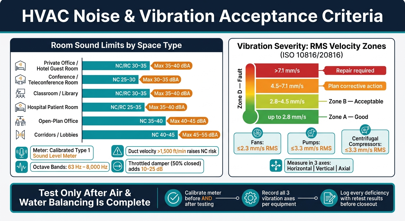
HVAC Noise & Vibration Acceptance Criteria: Key Thresholds at a Glance
How to Measure Noise: Meter Type, Locations, and NC Evaluation
Field noise testing starts with two basics for HVAC compliance: the correct meter and the correct test setup. TAB technicians use a calibrated Type 1 sound level meter with octave-band analysis from 63 Hz to 8,000 Hz. The meter should be field-calibrated before and after testing with a 94 dB, 1,000 Hz calibrator. For steady HVAC background noise, set the response time to slow.
Where you place the microphone matters just as much as the meter itself. Take readings about 4 to 5 ft above the finished floor and at least 3 ft from walls, corners, and other large reflective surfaces. In bigger rooms, one reading isn’t enough. Use multiple measurement points so the data reflects the occupied space, not just one spot near a diffuser or return.
Use octave-band data to check the measured sound against the specified NC or RC curve. NC is the highest curve not exceeded in any band. RC adds another layer by helping flag rumble and hiss.
Typical targets are below, but the project specification always controls.
| Space Type | Typical NC/RC Target | Typical Max dBA | Measurement Note |
|---|---|---|---|
| Private office / hotel guest room | NC/RC 30–35 | 35–40 | Measure at occupant height; use octave-band comparison |
| Conference / teleconference room | NC 25–30 | 30–35 | Background noise must be below the criterion to verify compliance |
| Classroom / library | NC/RC 30–35 | 35–40 | Check octave-band levels for dominant bands |
| Hospital patient room | NC/RC 25–35 | 35–40 | RC is helpful when tonal noise is noticeable |
| Open-plan office | NC 35–40 | 40–45 | Use multiple points in larger floor plates |
| Corridors / lobbies | NC 40–45 | 45–55 | Confirm the project spec before accepting elevated readings |
It also helps to verify the ambient background with the HVAC system off. If other sound sources are close to the limit, retest when conditions are quieter. That’s how you separate a system issue from plain old background noise.
How to Measure Vibration: Readings, Axes, and Equipment Conditions
Vibration testing uses a vibration meter or accelerometer mounted on bearing housings, motor bases, frames, or base plates. Take readings on a clean, flat, unpainted surface using a magnetic base or another secure mount so contact stays repeatable. Don’t measure on shafts or other moving parts.
Measure vibration in horizontal, vertical, and axial directions. Each axis can tell you something different. High axial vibration often points to alignment trouble, while high vertical vibration can point to support stiffness issues. Record data only after the equipment is running at its normal operating speed, load, and temperature.
Report vibration as RMS velocity in mm/s or in/s. That’s the standard severity measure for HVAC rotating equipment.
| Equipment Type | Primary Measurement Points | Key Interpretation Note |
|---|---|---|
| Centrifugal fan / AHU | Fan bearing housing, motor bearing, structural frame | Check all three axes; high axial values can indicate alignment issues |
| Centrifugal pump | Bearing housing, pump casing, base plate | Broad-band high values can indicate looseness or resonance |
| Chiller compressor | Compressor support, motor bearing | Manufacturer limits often govern; confirm against the spec |
Acceptance Criteria Used in TAB and Commissioning
Pass or fail comes down to the specified limit, where the test was taken, meter calibration, and whether the equipment was under normal operating conditions. For noise, acceptance may be based on an NC or RC limit, a maximum dBA level, or both.
For vibration, common ASHRAE guidance puts allowable RMS velocity at about 2.3 mm/s for fans and 3.3 mm/s for pumps and centrifugal compressors. ISO 10816/20816 uses severity zones to describe machine condition:
| Severity Zone | RMS Velocity (mm/s) | Interpretation |
|---|---|---|
| Zone A – Good | up to about 2.8 | New or very good condition |
| Zone B – Acceptable | 2.8–4.5 | Suitable for unrestricted long-term operation |
| Zone C – Alert | 4.5–7.1 | Unsatisfactory; plan corrective action |
| Zone D – Fault | >7.1 | Unacceptable; repair is needed |
Any Zone C or D vibration reading, or any noise result above the project limit, calls for correction and a retest under the same conditions. A fan can pass overall dBA and still fail NC if a narrow-band peak pushes one octave band too high. The same goes for a pump with modest overall vibration but one unusually high axial reading. In both cases, it’s still a failure, and it has to be fixed before closeout.
Common Problem Sources and Corrective Actions
When readings miss NC or vibration limits, TAB stops being just a measurement job. At that point, it turns into diagnosis.
Noise Problems Found During TAB
One of the most common issues in TAB is diffuser noise tied to air moving too fast, often because duct velocity is too high. Main duct velocities above 1,500 ft/min can create turbulent broadband noise that pushes room NC above the design target. Branch ducts are often held below 800 ft/min to help keep terminal noise under control.
Another problem shows up all the time: damper position. It’s easy to miss, but it matters a lot. A balancing damper throttled to about 50% closed can add 10–25 dB of noise because the pressure drop across the blades creates more turbulence. A better fix is to rebalance with the index run damper almost wide open, then cut fan speed to bring airflow back to design and reduce noise at the same time.
Duct layout can also make things worse. A mitered 90° elbow without turning vanes can add +5 to +12 dB of regenerated noise compared with straight duct at the same velocity. Add turning vanes, and that penalty drops to about +2 to +4 dB. Crushed or kinked flexible duct can do the same kind of damage near terminals. Breakout noise matters too. As duct velocity goes up, fan sound radiating through the duct wall into nearby rooms tends to go up as well.
Low-frequency noise can be tougher to pin down. Compressor hum and pump cavitation are common examples. If cavitation is on the table, check suction pressure and flow against the manufacturer’s operating window before chasing other causes.
If the noise doesn’t track back to airflow, the next place to look is mechanical vibration or unstable rotating equipment.
Vibration Problems Found During TAB
Fan imbalance usually appears as high amplitude at 1× rotational speed on the fan bearing housing, most often highest in the radial direction. One common cause is dirt buildup on the fan blades. In the field, cleaning the blades and then retesting is a simple way to see if imbalance is the root issue.
Shaft misalignment often shows up as high axial vibration at the coupling, along with harmonics at running speed. For pumps over 10 HP, straight-edge alignment often isn’t accurate enough for TAB acceptance. In most cases, laser alignment tools are needed. Soft foot is another one to watch for. If one motor or fan foot doesn’t sit flat, bolt load can warp the housing and create internal misalignment. Shim the bad foot, retest, and you’ll know pretty fast if that was the source.
VFD-driven fans and pumps can be sneaky. They may look fine at partial load, then fail at design speed when resonance or support issues show up. That’s why it helps to test at minimum, typical, and maximum operating speeds before the space is occupied.
Design Corrections vs. Operational Adjustments
Once you find the cause, the fix usually lands in one of two buckets.
TAB reports should log measured values, adjustments made, any deficiencies still left, and the next steps being recommended.
| Fix Type | Examples | Pros | Cons | Schedule Impact | Long-Term Performance |
|---|---|---|---|---|---|
| Operational adjustment | VFD speed reduction, damper reset, control sequence tuning | Low cost, fast | May reduce capacity margin | Minimal | Good if system is near design |
| Mechanical correction | Field balancing, laser alignment, bearing replacement, soft-foot shimming | Restores peak condition | Requires specialized tools and technicians | Moderate | Strong; addresses root cause |
| Design correction | Duct upsizing, transition improvements, isolator upgrades, inertia bases, support stiffening | Solves root cause; improves efficiency | Invasive; may need engineering review | High | Best long-term outcome |
Operational adjustments make sense when the system can still hit design airflow. Design corrections make more sense when staying in compliance means giving up too much capacity.
Whatever fix is chosen, it should be checked with repeat TAB readings under the same operating conditions.
Reporting, Final Inspection Coordination, and Conclusion
Coordinating TAB Results With Commissioning and Final Inspection
Noise and vibration testing doesn’t stop when the meter reading is taken. Once fixes are made, the updated records prove the issue was corrected and help support final acceptance. In practice, the results move through TAB, commissioning, the contractor team, and inspection review before the job can close out without loose ends. So closeout is as much about paperwork and retesting as it is about field testing.
Schedule testing only after air and water balancing is finished and the systems are stable at design operation.
The table below shows how closeout duties line up with each project phase.
| Project Phase | Noise & Vibration Tasks | Primary Responsible Party | Deliverables |
|---|---|---|---|
| Design Development | Set NC/RC/dBA and vibration limits; specify instrumentation | Engineer of Record | Design criteria memo; OPR noise/vibration targets |
| Preconstruction | Review submittals for fans, isolators; confirm TAB scope | TAB Agency, Commissioning Authority | Commissioning plan; TAB procedure with noise/vibration tasks |
| Pre-functional Testing | Verify ductwork, isolation, and access are complete | Mechanical Contractor | System ready for testing |
| Functional Testing / TAB | Room sound, source sound, and vibration tests at design conditions | TAB Agency (witnessed by Commissioning Authority) | Field test reports; deficiency log with equipment tags and locations |
| Correction Phase | Correct deficiencies and retest under the original conditions | Mechanical Contractor | Corrective action log; retest request |
| Pre-final Inspection | Retest failed items; confirm all deficiency log entries are closed | TAB Agency | Verified retest results; updated deficiency log |
| Final Inspection / Closeout | Submit the closed TAB report and commissioning summary for final review | General Contractor, TAB Agency | Certified TAB report; Certificate of Occupancy support |
When a reading fails, log the deficiency right away with the equipment tag, location, and suspected cause. The commissioning authority then adds it to the commissioning issue log, and the mechanical contractor digs into the root cause. After the fix is in, the TAB team retests under the same operating conditions used in the first test. Final inspection shouldn’t be scheduled until every critical item in the deficiency log is marked closed and includes retest data.
How Air Balance Masters Supports Closeout Documentation
Once deficiencies are closed, the last job is putting the results together for inspection.
Air Balance Masters is a certified air balance company serving HVAC and general contractors across MD, VA, PA, NJ, NY, DE, and DC. Air Balance Masters provides certified TAB reports, calibrated instrument records, deficiency logs, and retest documentation that contractors can submit during closeout and inspection review.
Key Takeaways for Reliable TAB Noise and Vibration Testing
These steps give contractors the clearest path from a failed reading to final sign-off.
Set project-specific noise and vibration criteria early, and test only after systems are balanced and operating at design conditions.
Use calibrated instruments and standardized methods. Record instrument make, model, serial number, and calibration date in every report. Follow recognized test standards, use the same measurement locations and axes each time, and compare results against the exact criteria listed in the project specifications.
Close every deficiency before final inspection. Every failed reading needs a unique ID, a root cause, a responsible party, a corrective action, and a retest result. A clean, fully closed log is what moves a project from partial completion to final acceptance without reinspection risk.
FAQs
Why must noise and vibration testing happen after TAB is finished?
Noise and vibration testing should happen after TAB is complete. That’s because the system needs to run under its intended design conditions, with all settings finalized and locked in.
TAB involves fine-tuning items like fan speeds and dampers. So if you test too early, your readings may not match how the system will actually run day to day. Testing at the end makes sure the results reflect the system’s final balanced state and confirm that comfort meets specifications before final inspection.
What causes an HVAC system to fail noise or vibration testing?
An HVAC system usually fails noise or vibration testing when mechanical stress or installation problems push it past its design limits.
Common causes include:
- improper fan alignment
- incorrect belt tension
- poor lubrication
- turbulent airflow caused by sharp duct turns near fan outlets
- badly adjusted or poorly maintained vibration eliminators that allow motor and fan energy to travel through the building structure
When that happens, the system doesn’t just sound louder. It can shake, hum, or pass vibration into walls, floors, and nearby spaces.
What should a TAB noise and vibration report include?
A TAB noise and vibration report should record measured noise levels along with key HVAC data, such as fan RPM, motor voltage and amperage, static pressure, airflow, and temperature.
It should also include calibration records, instrument serial numbers, any adjustments made, as-found and as-left conditions, unresolved issues with corrective recommendations, test point drawings, and a certified professional’s signature and seal.


