


HVAC systems need to perform as designed to ensure comfort, efficiency, and compliance with codes. Verifying HVAC design intent involves five key steps to align installed systems with the project’s goals and technical specifications. Skipping this process can lead to costly issues like poor air quality, energy waste, and inspection delays. Here’s a quick breakdown:
- Review Design Documentation: Analyze the Owner’s Project Requirements (OPR) and Basis of Design (BoD) to understand system goals and benchmarks.
- Inspect Equipment Installation: Confirm all components are installed as per design, using pre-functional checklists to prepare for testing.
- Verify Sensor Calibration: Ensure sensors provide accurate data for the Building Automation System (BAS) to avoid inefficiencies.
- Validate Control Sequences: Test the Building Management System (BMS) to confirm HVAC systems respond correctly to real-world conditions.
- Balance Air and Water Flows (TAB): Fine-tune airflow and water flow rates to match design specifications, ensuring proper system performance.
Without proper verification, systems may fail inspections, delay occupancy approvals, and increase operating costs. Certified TAB services, like those offered by Air Balance Masters, help projects meet these requirements efficiently and avoid setbacks.
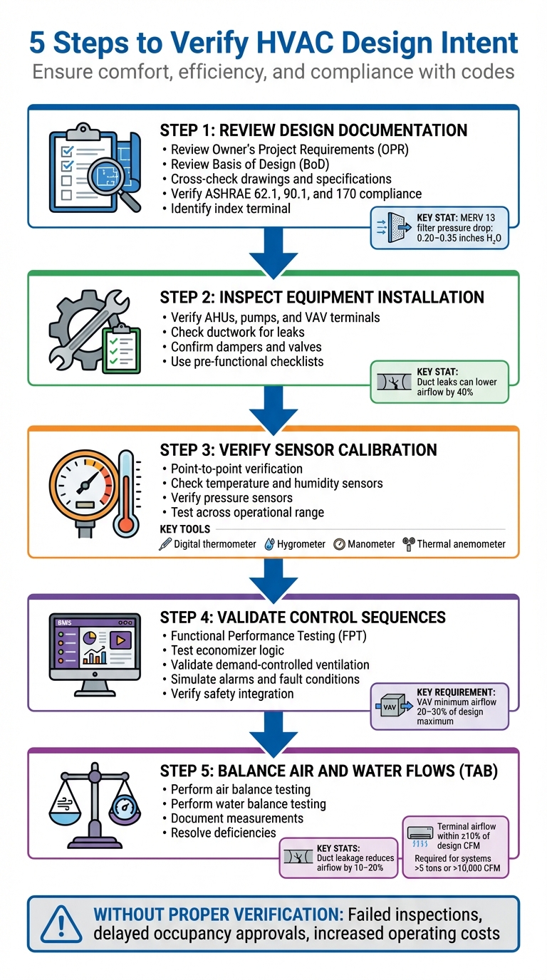
5-Step HVAC Design Intent Verification Process
How HVAC Systems are Designed, Installed & Commissioned: A Step-by-Step Guide🏢❄️ #hvac #hvacsystems
Understanding these phases helps facility managers troubleshoot common HVAC problems that often stem from design or installation gaps.
Step 1: Review Design Documentation
The first step in verification is a thorough desk review. Design documents serve as the foundation for evaluating system performance – without them, there’s no clear benchmark for success. The Owner’s Project Requirements (OPR) and Basis of Design (BoD) lay out the project’s objectives and the technical methods to achieve them. Together, they define both the goals and the approach, providing a roadmap for the entire process.
Review Owner’s Project Requirements (OPR) and Basis of Design (BoD)
The OPR outlines the project’s overarching goals, including targets for indoor air quality, thermal comfort, and energy efficiency. The BoD, on the other hand, details the strategies and technical decisions – like equipment sizing, zoning, control sequences, and ventilation rates – that the design team will use to meet those goals. These documents form the standard against which all measurements and adjustments are made.
"Commissioning ensures that all HVAC components are installed, tested, and operated according to the design intent – and according to guidelines like ASHREA Guideline 0." – CxPlanner
Design documents also include equipment schedules that specify airflow rates in cubic feet per minute (CFM) for diffusers, grilles, and registers. These schedules also provide fan performance data, such as design RPM, total external static pressure (TESP), and manufacturer fan curves. For specialized environments like hospitals, the BoD must confirm compliance with ASHRAE 170, which governs air change rates and directional pressure relationships. For general commercial projects, ASHRAE 62.1 and ASHRAE 90.1 are typically referenced for ventilation and energy efficiency standards, respectively.
Cross-Check Drawings and Specifications
Once the OPR and BoD have been reviewed, the next step is to ensure that the physical drawings align with these specifications. This involves comparing mechanical drawings with equipment schedules to confirm that duct layouts, damper placements, sensor locations, and terminal CFM values match. Discrepancies can arise when equipment schedules list specific CFM targets that don’t align with the duct sizing shown in the drawings. Such mismatches can lead to velocity issues or static pressure problems.
To streamline this process, gather all relevant documents upfront, including mechanical drawings, equipment schedules, duct layouts, and airflow tables. Verify that installed filters meet the specified MERV rating in the contract documents. For example, a MERV 13 filter may cause a pressure drop of 0.20–0.35 inches of water column. Additionally, identify the index terminal – the terminal with the highest design CFM demand relative to available static pressure. This terminal acts as a guide for balancing airflow and spotting potential bottlenecks before moving into fieldwork.
Step 2: Inspect Equipment Installation
Once the design documentation has been reviewed, the next step is to verify that the installation aligns with the approved plans. Field inspections are crucial here – they ensure that all physical components meet the specifications and are ready for functional testing. This process helps catch installation mistakes early, preventing larger issues during commissioning. Essentially, these inspections connect the design goals with the actual on-site setup, laying the groundwork for a smooth system commissioning process.
Verify Installation of Key Components
Start by checking that all major equipment is installed according to the design specifications. For air handling units (AHUs), this means confirming details like fan drives, motor amperage, and fan RPM against the manufacturer’s fan curves. Record initial fan RPM, total external static pressure (TESP), and motor amperage to establish a baseline for future reference. Pumps also need close attention – verify that impeller sizes match the approved submittals, as an incorrect impeller can disrupt the system’s ability to reach the required water flow rates.
VAV terminal boxes are another critical focus. Confirm that actuator positions match the building automation system (BAS) reports and check that the minimum and maximum airflow setpoints are correctly programmed. Inspect ductwork to ensure it is fully connected and free of leaks – leaks can lower airflow by as much as 40%. Additionally, confirm that filters are installed with the correct MERV rating specified in the design.
Dampers and valves should also be inspected to ensure they are set to the correct operational positions. Manual volume dampers, for instance, should initially be fully open, while fire and smoke dampers must comply with NFPA 90A life safety standards. Be sure to document equipment model numbers, voltage, and amperage as outlined in the design documents.
Once these components are verified, use pre-functional checklists to confirm everything is ready for testing.
Use Pre-Functional Checklists
After confirming the physical installation, pre-functional checklists are used to ensure that each component is energized and ready for detailed testing. These checklists verify that mechanical systems are complete – equipment is powered, controls are operational, and the system is prepared for commissioning. They also confirm that filters and coils are clean, which is critical for obtaining accurate test results.
Standardized checklists help align the installation with the Owner’s Project Requirements (OPR) and Basis of Design (BoD). Completing these checklists is a prerequisite for commissioning, as per ASHRAE Guideline 0, which states that a building cannot be fully commissioned without verified installation and TAB (Testing, Adjusting, and Balancing). Digital tools simplify this process by enabling real-time data entry, reducing manual errors, and ensuring compliance with NEBB or AABC standards.
Step 3: Verify Sensor Calibration
Once the equipment installation is confirmed, the next step is to ensure all sensors are properly calibrated. Think of sensors as the HVAC system’s eyes and ears – they gather critical data for the Building Automation System (BAS), which manages everything from temperature settings to ventilation rates. Even a slight inaccuracy, like a sensor being off by a few degrees or a small pressure misreading, can disrupt system efficiency, waste energy, and affect occupant comfort.
Calibration ensures that the sensor readings align with what the BAS reports. This process, often referred to as point-to-point verification, helps identify issues such as signal loss or scaling errors between the field device and the control system. It’s a key step that connects the system’s design goals with its actual performance, ensuring the data used for control decisions is accurate. Skipping this step could mean having sensors that seem functional but provide inaccurate data, leading to poorly executed control sequences.
Check Temperature and Humidity Sensors
Start by comparing the readings from installed sensors with calibrated handheld instruments placed in the same location. Use tools like digital thermometers for temperature, hygrometers or psychrometers for humidity, and digital manometers or differential pressure gauges for pressure. Be sure these instruments have been calibrated within the past 12 months, following NEBB or AABC standards.
Proper sensor placement is crucial. Confirm that sensors are installed in locations that provide accurate environmental data. Avoid placing them in areas like stagnant air zones, direct sunlight, or near heat-emitting equipment, as these can distort readings. For pressure sensors, measure differentials across components such as filters and coils to verify performance against the system’s design specifications.
Test sensors across their entire operational range – both high and low extremes – to ensure accuracy under all conditions. This step guarantees consistent sensor performance throughout the system’s control sequences, aligning with earlier design verification efforts. Document any calibration offsets applied in the BAS, as these records establish a baseline for future maintenance and recalibration. For Variable Air Volume (VAV) systems, check that actuator positions and BAS airflow readings match physical measurements taken at the terminal using tools like thermal anemometers for low-velocity airflows.
| Sensor Type | Verification Tool | Purpose |
|---|---|---|
| Temperature | Digital Thermometer | Verifies heating and cooling accuracy |
| Humidity | Hygrometer / Psychrometer | Ensures proper indoor air quality and comfort |
| Pressure | Manometer / Differential Pressure Gauge | Measures static and differential pressures |
| Airflow | Thermal Anemometer / Flow Hood | Confirms air distribution and terminal airflow rates |
Step 4: Validate Control Sequences
Once you’ve confirmed the sensors are working correctly, it’s time to focus on the Building Management System (BMS) control sequences. These sequences are essentially the instructions that guide your HVAC system’s response to changing conditions. This phase, called Functional Performance Testing (FPT), ensures that the entire system operates as intended under real-world conditions. If these sequences aren’t validated, even the best-installed equipment and precisely calibrated sensors won’t perform as expected.
"The sequence of operation is one of the most important design aspects of any HVAC system. Without a proper sequence, the system is left to operate wildly – or not at all."
- Consulting, Specifying Engineer
Start by developing a points list matrix. This document identifies all the digital and analog inputs (data received by the BMS) and outputs (signals the BMS sends to equipment). Think of this matrix as your testing blueprint. Work step-by-step through each sequence, verifying that the BMS processes measured values against setpoints correctly. For example, check that a chilled water valve adjusts when the space temperature exceeds its setpoint. Be sure to test compliance with energy code requirements, including economizer functions, demand-controlled ventilation (DCV), supply air temperature adjustments, and setbacks.
Test Economizer Logic and Ventilation Modes
Economizers help reduce energy use by utilizing outdoor air for cooling when conditions allow. To test this, simulate different outdoor air temperatures and confirm that dampers react appropriately – opening for cooling when conditions are favorable and closing when they’re not. Also, ensure the system shifts smoothly between occupied and unoccupied modes, applying necessary setbacks during unoccupied periods.
For demand-controlled ventilation, check that CO₂ sensors trigger increased outdoor air intake in response to occupancy changes. The system should maintain the desired levels for space temperature, duct static pressure, and CO₂ concentrations as outlined in the design intent. If you’re working with Variable Air Volume (VAV) systems, test their performance at minimum airflow setpoints – typically 20–30% of the design maximum. Even at reduced flow rates, they should still meet ventilation and comfort requirements.
Simulate Alarms and Fault Conditions
Validating how the system handles faults is just as crucial as testing its normal operation. Simulate alarms manually to ensure the BMS executes the correct responses. For instance, mimic a dirty filter condition using the differential pressure switch and confirm that the system generates an alert. Test smoke detection functionality to verify that proper shutdown sequences occur when smoke is detected.
Safety integration needs careful attention too. Test sequences to confirm coordination with fire alarms, smoke control systems, and emergency shutdowns. These tests are often required for inspections by the Authority Having Jurisdiction (AHJ) and are critical for permit finalization. Additionally, document all trending data with appropriate sampling intervals – typically every 15 minutes – and retain it for 30 to 90 days. This helps monitor long-term performance and spot any deviations in the sequences.
| Point Type | Example Component | Signal Type |
|---|---|---|
| Digital Input | Dirty filter alarm (pressure switch) | On/Off (0 or 1) |
| Analog Input | Space temperature sensor | Voltage/Amperage range |
| Digital Output | Exhaust fan start/stop | On/Off (0 or 1) |
| Analog Output | Chilled water valve position | 0% to 100% open |
Step 5: Balance Air and Water Flows
Once you’ve validated control sequences, the next critical step in commissioning is to perform Testing, Adjusting, and Balancing (TAB) to fine-tune air and water flows. Without this process, even the best-installed equipment and perfectly calibrated sensors won’t achieve the intended performance. For instance, duct leakage in commercial buildings can cut delivered airflow by 10–20% compared to fan output.
"TAB is a prerequisite for commissioning, not a substitute. A building that passes functional performance testing without completed TAB is not considered commissioned."
- HVAC Compliance Authority
TAB ensures that all terminal units, diffusers, and hydronic circuits meet the flow rates specified in the design documents. This process aligns measured performance with the design intent, guaranteeing occupant comfort while meeting regulatory standards. For example, ASHRAE 90.1-2022, Section 6.4.3, requires system balancing for commercial HVAC setups, and many jurisdictions demand a certified TAB report to issue a Certificate of Occupancy.
Perform Air Balance Testing
Start by preparing the system. Confirm that ductwork is properly connected, filters are installed correctly, and controls are operational. Ensure your instruments – such as pitot tubes, flow hoods, and manometers – were calibrated within the last 12 months. Keep in mind that a dirty MERV 13 filter can create a pressure drop of 0.20–0.35 inches of water column, significantly lowering airflow.
Begin air balancing with fan performance testing. Measure static pressure, RPM, and total CFM using duct traversal methods, typically employing a pitot tube grid based on log-linear or log-Tchebycheff patterns. Match these readings against the manufacturer’s fan curve to confirm the fan is working at its design point. Then, use proportional balancing, starting at the index terminal (the unit with the highest demand), to adjust flows across the system.
Avoid adjusting dampers in isolation. Closing one damper can increase upstream static pressure, unintentionally boosting airflow at other terminals. Instead, adjust dampers proportionally, ensuring flow ratios align with the design intent. Terminal airflow should stay within ±10% of the design CFM. For multi-cone or high-induction diffusers, use published K-factors for accuracy.
If a terminal underperforms, check for duct leakage before increasing fan speed. Higher speeds can worsen leakage losses, which increase with the square of velocity. Also, confirm that VAV actuator settings align with BAS airflow data.
Once air balancing is complete, apply similar techniques to balance the hydronic circuits.
Perform Water Balance Testing
With air flows addressed, shift focus to the hydronic system. Use mechanical drawings and equipment schedules to identify target flow rates (measured in gallons per minute). Before starting, make sure coils, heat exchangers, and valves are functioning properly.
Identify the "index circuit" – the branch with the highest pressure drop – and start proportional balancing from there. Use calibrated ultrasonic flow meters for noninvasive flow measurements, and adjust balancing valves proportionally to meet the design intent. Since adjusting one valve can impact pressure and flow throughout the system, iterative measurements may be necessary.
Check pump performance by reviewing impellers and VFD settings to ensure the system meets the required GPM and head specifications. Once flow rates are finalized, lock all balancing valves in place to prevent drift.
Document Measurements and Resolve Deficiencies
Thorough documentation is a must. Record all measurements, equipment data, and any deviations from the design intent following AABC/NEBB standards. The TAB report should include details like fan performance (RPM, static pressure, amperage), terminal values (CFM, FPM), equipment data, and instrument serial numbers.
If issues arise, use root cause analysis to address them. For example, if airflow is below expectations, look for undersized ducts, dirty filters causing excessive pressure drops, or duct leakage instead of simply increasing fan speed. Cross-check your measurements with BAS data to ensure consistency.
In most jurisdictions, the TAB report is a key compliance document for closing out permits. Inspectors often verify the existence of a certified report rather than re-measuring flows themselves. This report supports compliance with ASHRAE 90.1-2022 and local regulations. Some areas even require third-party TAB for systems exceeding 5 tons of cooling capacity or 10,000 CFM of supply airflow. For large rectangular ducts, standardized duct traversal may require at least 16 measurement points to ensure accuracy.
How Air Balance Masters Supports HVAC Design Intent Verification
Air Balance Masters offers certified TAB testing and reporting services across MD, VA, PA, NJ, NY, DE, and DC. Their quick turnaround ensures TAB reports are ready within 48 hours, speeding up final inspections and helping secure Certificates of Occupancy without delay.
When systems fail to meet design specifications, the company provides detailed deficiency reports. For issues like insufficient airflow or underperforming hydronic circuits, their technicians dig into the root causes – whether it’s duct leakage, undersized components, or fan wear – and suggest actionable fixes. This approach reduces the likelihood of expensive callbacks and helps keep projects on track.
"We help you pass final inspections and get your Certificate of Occupancy – fast."
- Air Balance Masters
With certifications from NEBB, NCI, BPI, and AEE, Air Balance Masters follows ASHRAE, NEBB, and AABC standards. They also specialize in healthcare projects, ensuring compliance with ASHRAE 170, TJC, and CMS requirements.
For contractors facing tight deadlines, expedited services are available. These include next-day appointments and same-day quotes, provided essential project details – such as system count, square footage, and register count – are submitted.
Verify design intent before closeout
Following a five-step process to verify HVAC design intent ensures that systems operate according to their specifications. This approach helps avoid common issues like occupant discomfort, wasted energy, and poor air quality.
Certified TAB (Testing, Adjusting, and Balancing) services play a key role in meeting both compliance requirements and performance standards. Many jurisdictions now mandate third-party TAB for commercial systems with over 5 tons of cooling capacity or supply airflow exceeding 10,000 CFM. Without a certified TAB report, you could face delays in obtaining a Certificate of Occupancy and incur additional costs during final inspections.
The numbers highlight the importance of verification. For example, ASHRAE reports that duct leakage can reduce airflow by 10%–20%, while a clogged MERV 13 filter may cause a pressure drop of 0.20–0.35 inches of water column. These problems often go unnoticed without thorough testing and measurement, reinforcing the value of certified TAB services during system commissioning.
Air Balance Masters provides certified TAB services across MD, VA, PA, NJ, NY, DE, and DC, adhering to ASHRAE, NEBB, and AABC standards. Their efficient TAB reporting helps projects stay on schedule, and their detailed deficiency reports help contractors address issues – like duct leakage, undersized components, or fan performance problems – before they lead to costly setbacks.
For contractors working under tight deadlines or needing to meet ASHRAE 170 standards, partnering with a certified TAB provider can ensure inspection approvals on the first attempt. Visit Air Balance Masters to request a quote and schedule your service today.
FAQs
When should HVAC design intent verification happen in a project?
Verifying the HVAC design intent should happen during the pre-TAB planning and preparation phase, well before the testing, adjusting, and balancing (TAB) process starts. This crucial step confirms the systems are ready for testing by ensuring the building envelope is properly sealed, all equipment is fully operational, and the necessary documentation has been reviewed. This preparation allows for an accurate evaluation of whether the HVAC systems align with the original design specifications.
What’s the difference between commissioning and TAB?
Commissioning is the process that ensures an HVAC system aligns with its design goals, operates as intended, and meets performance standards. This involves several stages, including planning, testing, and verification. A key component of this process is TAB (Testing, Adjusting, and Balancing). TAB specifically focuses on measuring and fine-tuning aspects like airflow, pressure, and temperature to match the system’s design specifications. Simply put, commissioning takes a broad approach to the entire system, while TAB zeroes in on achieving balance for optimal efficiency.
What are the most common reasons airflow or waterflow can’t hit design?
Issues with airflow or waterflow in HVAC systems often stem from problems related to balancing, adjusting, or testing the system. Common culprits include improperly calibrated measurement tools, unbalanced dampers or valves, and incomplete or incorrect documentation of system performance. Ensuring accurate testing and making precise adjustments are key steps to keep the system running as designed.


